Converting Parallel RL Circuits to their “Easier To Work With” Series Equivalents
In the fourth part of our series on Tips For Practicing Technicians, we look at a simple technique that can be used to simplify circuit analysis when working with series and parallel RL circuits. One of the issues encountered by technicians who are working with parallel RL circuits is the need to work with values that are the reciprocals of the more commonly used standard units. The use of conductance, susceptance, and admittance instead of resistance, reactance, and impedance, can often cause confusion or uncertainty when working with these lesser employed units. This conversion approach or technique can be especially helpful when working with circuits having multiple resistors and inductors in mixed series/parallel configurations. Reducing such a mixed topology network down to a few inductors and resistors in series greatly simplifies calculating overall resistance and inductance in a given circuit or network. In the series format, it is simply a matter of addition when calculating total inductive reactance, total resistance to get to overall impedance.
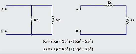
Below are the basic equations for creating a series representation of a given parallel RL circuit.
Performing the conversion...
Step 1: Calculate the equivalent resistance value Rs
Step 2: Calculate the equivalent inductive reactance Xs
Step 3: Calculate the required inductor value that will provide the appropriate series inductive reactance for a given frequency. Use L = XL / ( 2 * Pi * freq ) to obtain the inductor value.
Step 4: Redraw the circuit in a series configuration using the arrived at component values for the inductor and resistor.
Correctly employing the above steps will result in a series representation of a parallel RL circuit that behaves identically with respect to voltage, current, and the phase relationship between them. From the perspective of points A and B in the above, both circuits will result in identical behaviour.
Employing topology conversion techniques such as Parallel to Series RL circuit conversion, Delta-Wye conversions for resistor networks, or simple Source Transformations (converting current sources with parallel resistances to voltage sources with series resistances) is a common simplification tactic that can be extremely helpful in circuit reduction and analysis at a technician level. As a technician, the more tools you have at your disposal, the easier it will be to simplify and reduce complex circuits down to simple representations. This in turn will serve to reduce the chance of errors when performing technician level circuit analysis.
In the animation below, an example of performing the conversion from a parallel RL circuit to an equivalent series RL circuit is illustrated step by step when the resistance and inductive reactance is known for the given parallel RL circuit.
If you liked this post, check out our previous articles in The Practicing Technician Series;
Using the Natural Log or “ln” function in circuit analysis.
How to Create Correct Ohm's Law KCL Branch Equations for Nodal Analysis
How to Solve Simultaneous Equations with Multiple Unknowns
We hope this has been helpful to you as a practicing or student technician. We are looking for other ideas for this continuing Practicing Technician series. Please let us know what you would like us to write about by sending us your thoughts and questions at support@gbctechtraining.com.